Print the nuc tunnel adapters yourself
I am running a colony in my garage on the end of a three foot hose, and the reason for it is in the experiment write-up. This post is only the hardware, because people have asked and there is no reason to keep it.
Free, CC BY 4.0, print as many as you like. The set fits a five frame Pro Nuc.
Updated 3 September 2026. Version two is here. The plates now take a quick release hose connector, side latches, sliding doors, and a sensor chamber in the rear plug. Everything below describes v2.
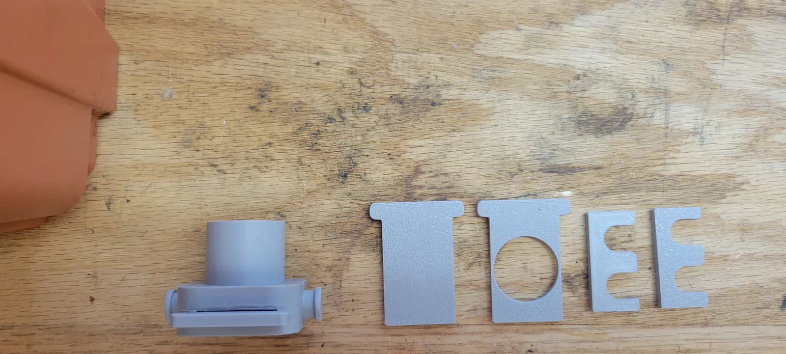
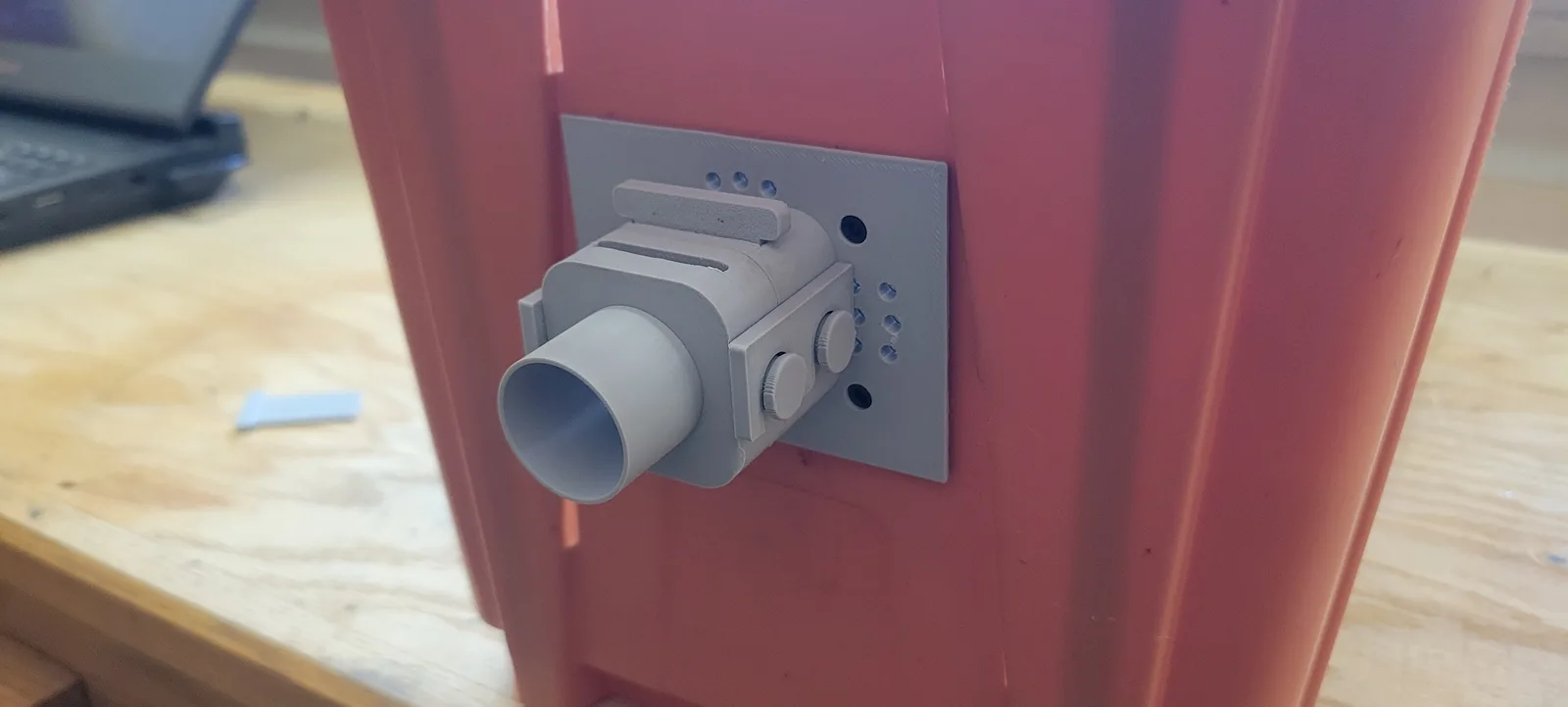
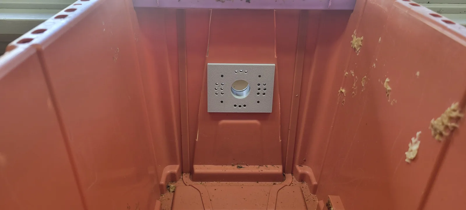
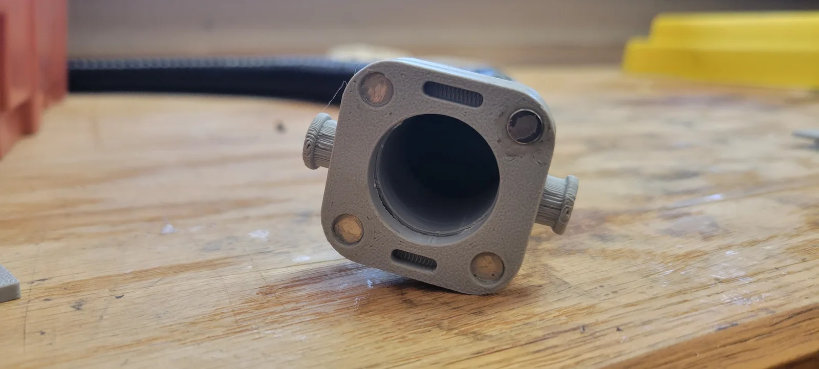
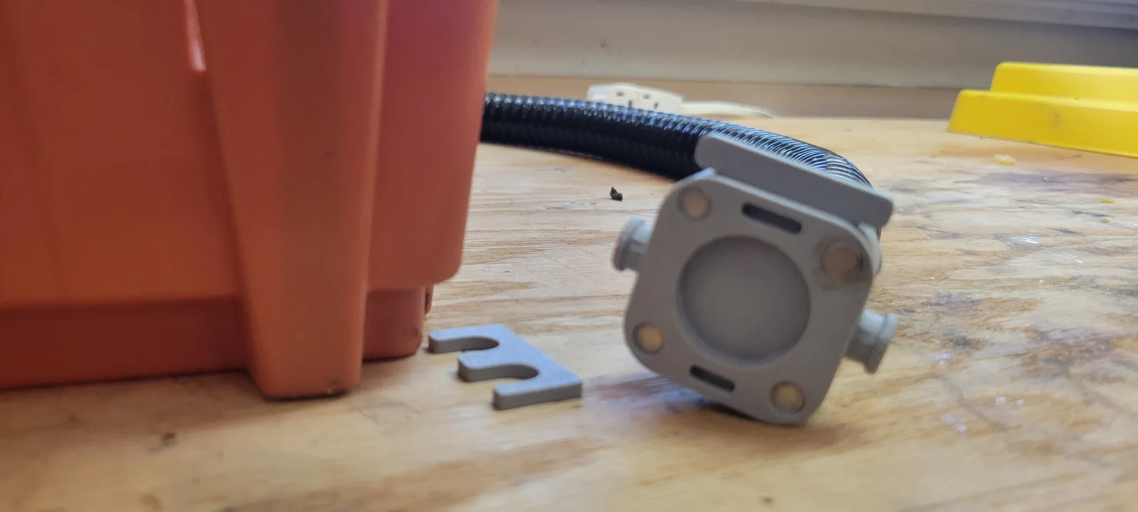
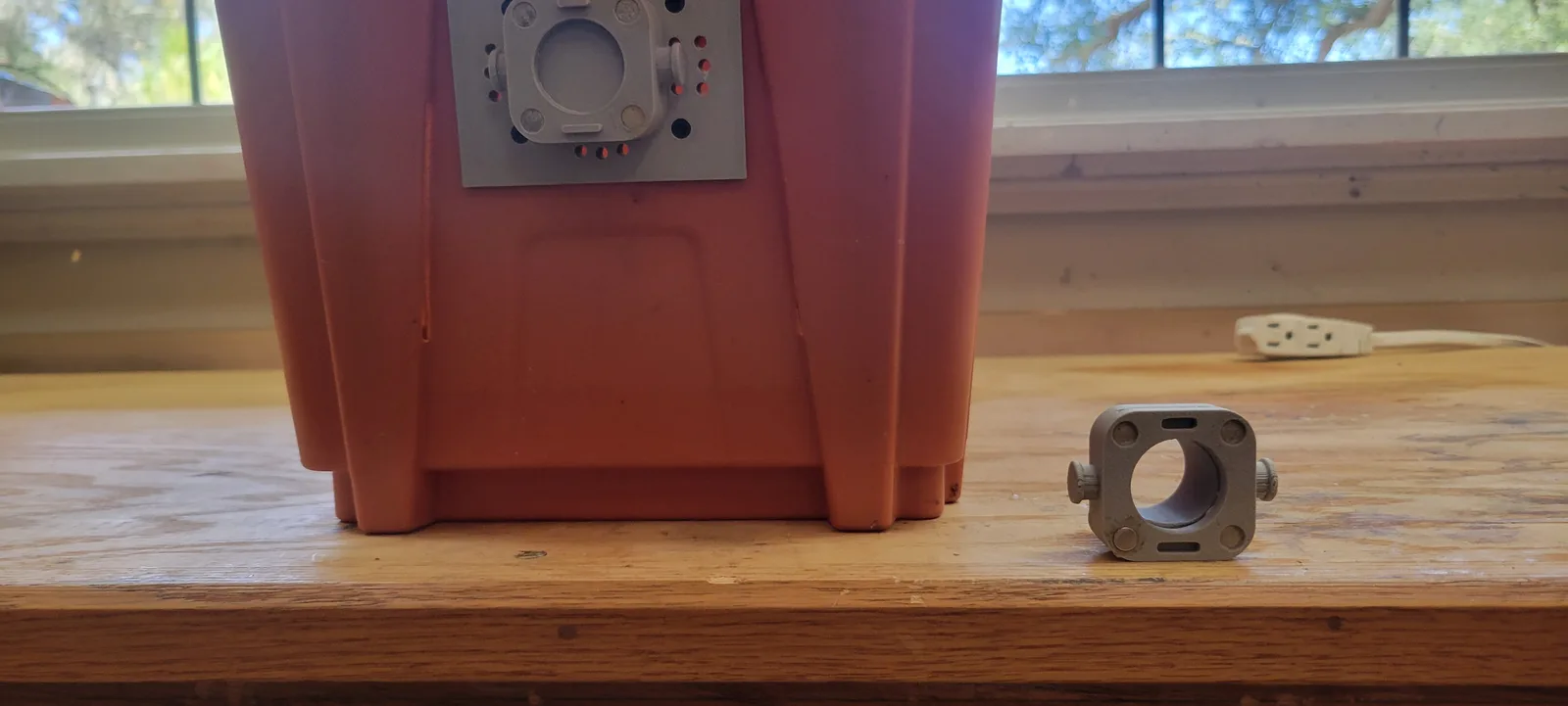
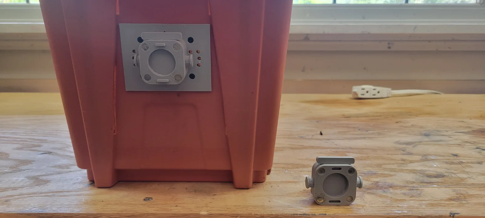
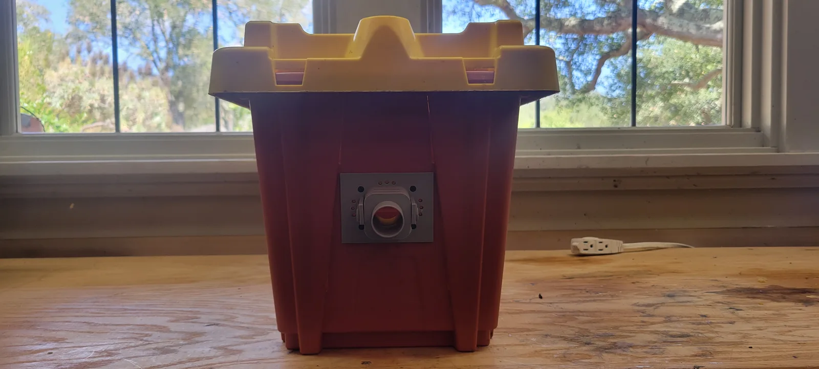
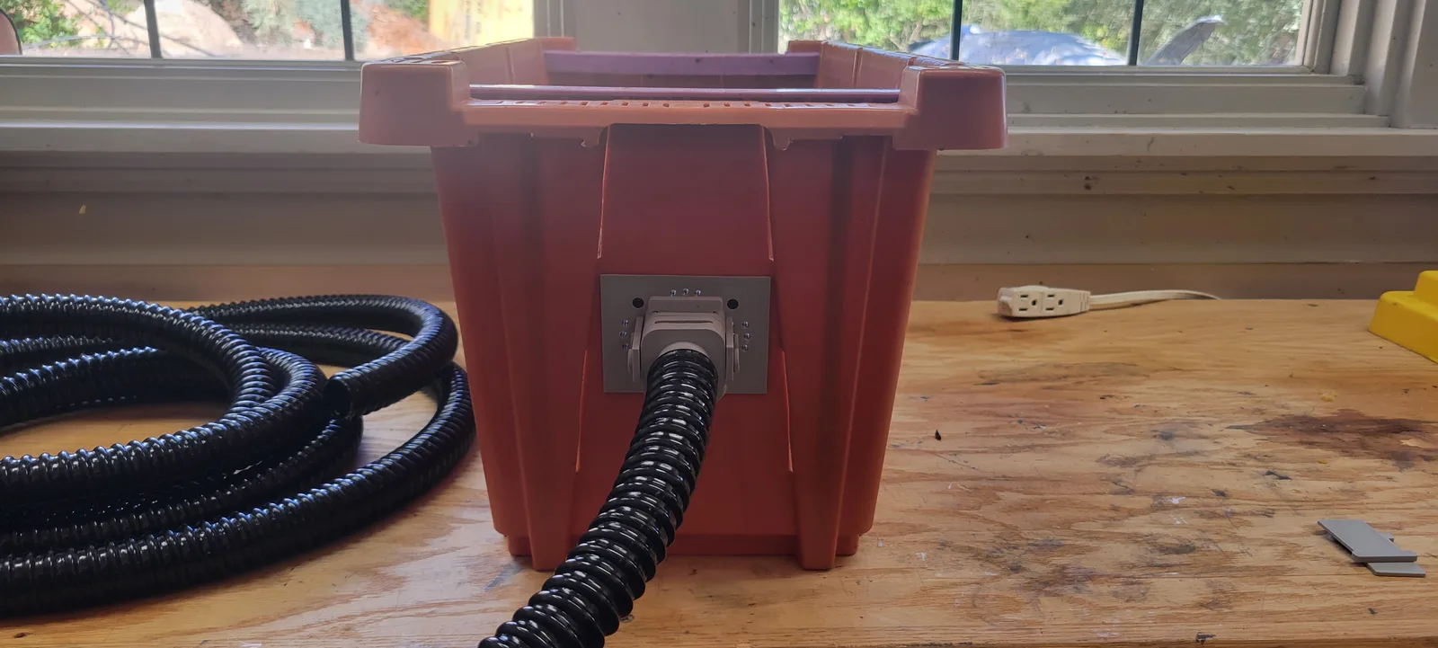
What the parts do
There are two jobs here. Getting the hose onto the box, and getting it through a wall.
At the box, adapters built as pairs of plates that sandwich the wall on M5 screws into brass heat set inserts. The threads live in brass, not in the print and not in the box, so nothing strips and nothing depends on the box wall holding a screw.
The plates are drawn around the openings the Pro Nuc already has. They slot into the existing holes. Nothing gets cut and nothing gets drilled. One adapter is the tunnel, the other closes the second opening so the box has exactly one way in and out. The whole assembly comes off again and leaves the box as it was.
At the wall, a deeper part that passes through and carries the landing ledge on the outside. That one is unchanged from version one.
The hole is 35 mm, and that is deliberate
The wall adapter is drawn to fill a 35 mm hole cut with a standard wood cutter. 35 mm is the standard cabinet hinge cup size, so it is a Forstner bit most people with a drill already own, and every hardware shop has one for a few dollars. No hole saw, no odd size, no ordering anything.
Note the two numbers are different. The bee opening is sized for 1 inch hose. The mounting hole is 35 mm. The 35 mm section fills the hole. The boss beyond it is what the hose grips.
The ledge is not decoration
On the first day, foragers came out of the tunnel onto it and stood there, and guard bees took up position on it within hours. A bee arriving at a hole with no lip has to fly into a 25 mm target. A bee arriving at a ledge can land short and walk in.
Magnets, keys and latches
The plates carry 6 x 1.45 mm neodymium magnets and a pair of alignment keys, 8 mm at the top and 10 mm at the bottom. The keys are different sizes on purpose, so the halves only go together one way and you cannot fit them upside down in poor light with bees in the air.
The magnets are not the fastening. They hold well enough to drag an empty box across a bench, and not well enough to trust. The side latches are what actually clamp it. With both engaged you can hang the whole box off the assembly and it does not move.
Print the magnet pockets slightly oversized and epoxy the magnets in. They self orient as the epoxy sets, so you do not have to get the polarity right by hand.
The doors, which turned out to be the useful part
Each adapter carries a 2 mm slot. A door slides into it and closes the colony off without smoke, without lifting a lid, and without disturbing anything. There are two, one solid and one with the opening left clear.
That single slot ended up doing more work than anything else in the design. It lets you shut the box to move it, shut it to swap a part, and shut it to work on the hose.
The point is not really the door. It is that a live colony can be carried out to a table, worked, and put back, and at no stage does anything have to be agitated to do it.
The sensors
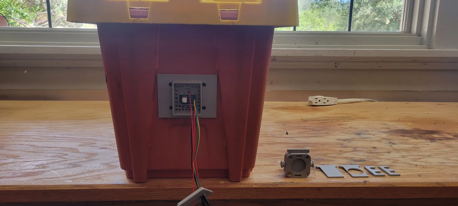
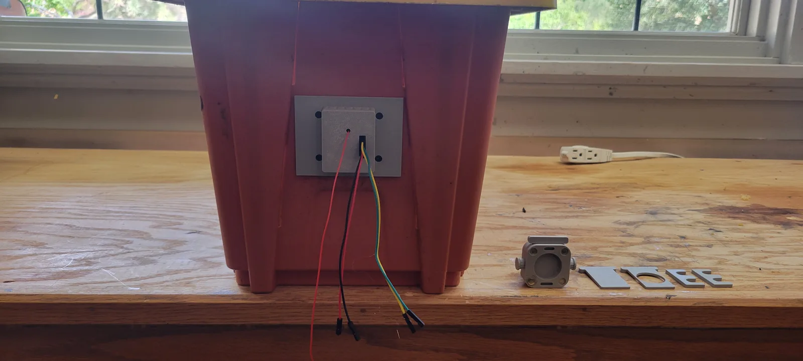
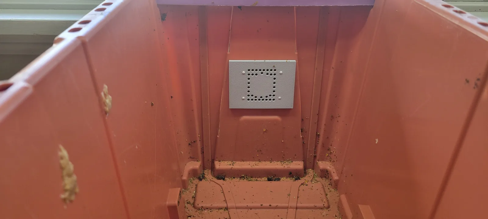
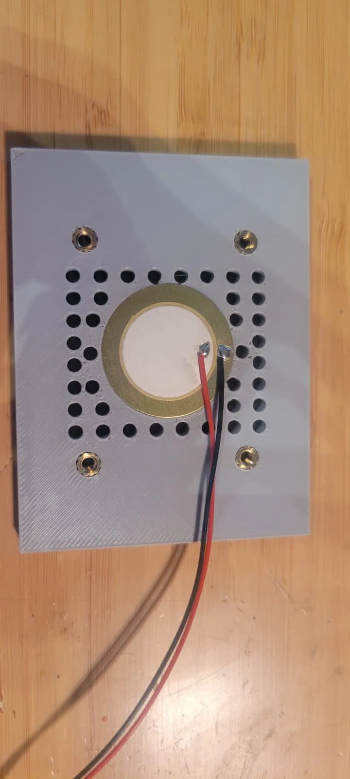
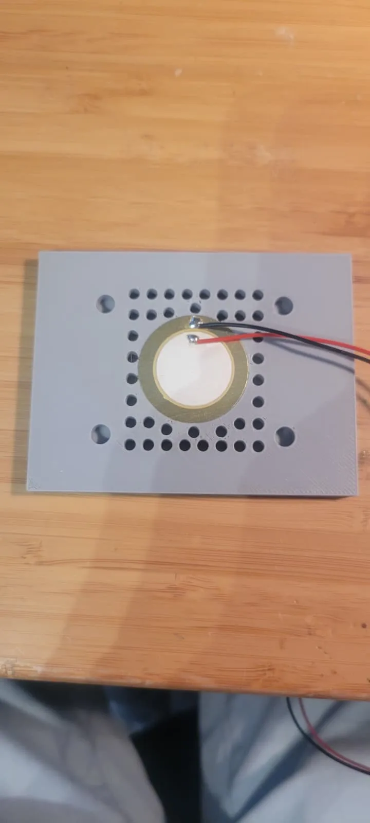
The rear plug is not just a plug any more. It carries a chamber for a CO2 sensor and a recessed pocket for a piezo disc.
Two Sensirion SCD41s, one behind the tunnel mouth and one in the rear chamber. Each reads CO2, temperature and humidity. The reason for two rather than one is that the difference between them says which way the colony is moving its air. Rear high and tunnel close to outside air means it is drawing in through the tunnel and venting out the back. If that reverses, so has the airflow, and I do not have to guess from watching bees fan at the entrance.
CO2 is standing in for something I cannot measure directly. The claim this whole design rests on is that a hose mouth on a wall is a low odour hole that robbers never learn about. Odour is expensive to measure. Odour travels in hive air, and CO2 is the cheapest honest marker of hive air there is. So CO2 at the mouth against outdoor background is a direct test of the premise. Sitting at background means the hole really is anonymous. Elevated means it is broadcasting, and the design is running on geometry and guards instead of on secrecy.
A 27 mm piezo disc sits in the rear plug as a contact microphone, sandwiched between the plates with a relief channel cut so the solder joints are not crushed when they close.
An ESP32 running ESPHome reads all of it, on two separate I2C buses, because both SCD41s answer to the same fixed address and it cannot be changed.
The sensor pocket is not required. If you only want the tunnel, print the rear plug and ignore the chamber.
Dimensions
| File | Size | What it is |
|---|---|---|
wall-landing-adapter.stl | 85.6 x 74.5 x 52 mm | Passes through the wall. Landing ledge outside, hose boss inside |
tunnel-front-outside.stl | 79.5 x 60.9 x 28.5 mm | At the box. Opening, vent holes and landing bar |
tunnel-front-inside.stl | 79.5 x 60.9 x 5 mm | The other half of that sandwich |
rear-plug-outside.stl | 79.5 x 60.9 x 17 mm | Closes the rear opening. Carries the sensor chamber |
rear-plug-inside.stl | 79.5 x 60.9 x 5 mm | The other half, with the piezo pocket |
hose-quick-connect.stl | 50 x 38 x 34.5 mm | Takes the hose, clips to the plate on two knobs |
security-latch.stl | 36 x 17 x 3 mm | Side latch. Print two |
door-solid.stl | 44 x 34 x 3.5 mm | Slides into the slot and closes the box |
door-passthrough.stl | 44 x 34 x 3.5 mm | Same door with the opening left clear |
The box plates are all 79.5 x 60.9 mm. The openings take 1 inch corrugated pond hose.
Hardware you need
M5 brass heat set inserts and M5 screws. Screw length depends on your box wall, since the plates sandwich it, so measure rather than take a number from me.
6 x 1.45 mm neodymium magnets for the alignment pockets.
Set the inserts with a soldering iron, ideally with an insert tip, and press them in while the plastic is soft rather than forcing them cold. In PETG they seat cleanly, and they are the reason this assembly comes on and off repeatedly without the fixings degrading, which a screw driven straight into plastic will not survive.
Printing
PETG, 15% infill, 0.2 mm layers. That is what mine are.
PETG rather than PLA is the one choice that matters, and it is not fussiness. The wall adapter sits on stucco in full afternoon sun, and PLA creeps at the temperatures a sunlit wall reaches on a summer afternoon. A part that softens and sags is a part that stops sealing the hole. PETG holds. ASA would too.
Nothing here is dimensionally fussy except the hose bosses and the 35 mm section, so 0.2 mm is not a requirement. Finer will not fit better and coarser will not fit worse.
One thing to think about before you slice the wall adapter. It has features on both faces, the landing ledge on the outside and the hose boss on the inside, so whichever way it goes on the bed, one of them is in the air. Decide which one you would rather support, and remember that the ledge is a surface bees stand on, so it wants to come off the printer clean.
A note on the hose
Ordinary 1 inch corrugated pond hose. I did not choose it for this and got lucky: the inside surface is extremely grippy, which gives bees good traction for the length of the tunnel. If you substitute something smooth, that is the property to check.
Download
- wall-landing-adapter.stl 93 KB
- tunnel-front-outside.stl 259 KB
- tunnel-front-inside.stl 142 KB
- rear-plug-outside.stl 517 KB
- rear-plug-inside.stl 226 KB
- hose-quick-connect.stl 144 KB
- security-latch.stl 25 KB
- door-solid.stl 10 KB
- door-passthrough.stl 26 KB
They are also on Printables, if you would rather download them there, post a print, or ask a question somewhere I will see it.
Licence: CC BY 4.0. Print them, sell them, modify them, send them to a printing service. The only condition is attribution, and a link back to this page is plenty.
What I do not know yet
The colony has been running through the wall since 31 August. The parts do what they were drawn to do: the bees found the tunnel on the day it was connected, they use the ledge, and the box has come on and off the assembly without incident.
Everything past that is open. The sensors are fitted but there is no data yet. Nothing has logged a full day.
The question I most want answered is whether the rear vent is an easier path for air than the tunnel, because on the first day the colony chose to move its air out through the tunnel instead, which is the opposite of what the design intends. That is what the two CO2 sensors are there to settle.
So print them knowing that. They are a working part, not a finished one.
The colony these came off is on a live camera, and the experiment they belong to is written up at Growing a nuc in the garage.